INFO@GRIKALIP.COM.TR - GET A QUOTE FOR YOUR PROJECTS BY CONTACTING US - INFO@GRIKALIP.COM.TR
Common Defects in Plastic Injection Molding
Problems such as sink marks, flash formation, short shots, burn marks, and warpage directly affect production quality. In this article, we share the causes of the most common injection molding defects and the methods used to solve them.
6/29/20269 min read
Common Defects in Plastic Injection Molding
Meta Title: Common Defects in Plastic Injection Molding | Gri Kalıp
Meta Description: Explore the causes and solution methods for common plastic injection molding defects such as sink marks, flash, short shots, burn marks, and warpage.
URL Slug: common-defects-in-plastic-injection-molding
Blog Card Short Description: Problems such as sink marks, flash formation, short shots, burn marks, and warpage directly affect production quality in plastic injection molding. In this article, we share the causes of the most common injection molding defects and the methods used to solve them.
Why Are Defect Causes Important in Plastic Injection Molding?
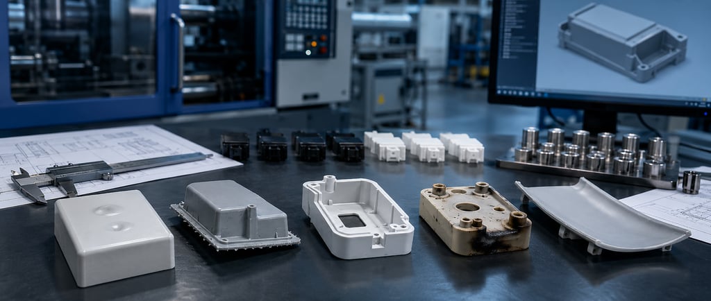
Plastic injection molding is a precise manufacturing method that requires correct mold design, suitable material selection, controlled process parameters, and regular quality control. If the product design is not properly prepared, the mold system is not well planned, or the injection parameters are not correctly adjusted, different quality problems may occur during production.
These defects should not be considered only as visual imperfections. Some injection molding defects may reduce the mechanical strength of the part, affect assembly compatibility, cause dimensional deviations, or shorten the product’s service life. Especially in automotive, home appliance, electrical and electronic, medical, packaging, and technical plastic part production, even a small defect can lead to significant costs in mass production.
In order to maintain sustainable quality in plastic injection molding, it is not enough to detect defects only at the end of production. The main priority is to correctly analyze the source of the defects and apply engineering solutions that prevent them from recurring.
1. Sink Marks
A sink mark is a visual defect that appears as a slight inward depression or waviness on the surface of a plastic part. It is usually seen in thick wall sections, around screw bosses, behind ribs, or in areas where material concentration is high.
As the plastic material cools inside the mold, it shrinks volumetrically. If some areas of the part are thicker than others, these areas cool more slowly and may cause sink marks on the surface. Sink marks become more visible especially on glossy or aesthetic surfaces.
Main Causes of Sink Marks
One of the most common causes of sink marks is unbalanced wall thickness. In plastic part design, wall thickness should be kept as uniform as possible. Excessively thick sections increase cooling time and create inward shrinkage on the surface.
Another cause is insufficient holding pressure. After the mold cavity is filled during injection, holding pressure is applied to compensate for material shrinkage. If the holding pressure is too low or the holding time is too short, the risk of sink marks increases.
An insufficient or unbalanced cooling system may also cause sink marks. If some areas inside the mold remain hotter than others, the part does not cool uniformly and surface quality may be affected.
Solution Methods
To reduce sink marks, the part design should first be reviewed. Unnecessary thick sections should be cored out, rib thicknesses should be balanced according to the main wall thickness, and screw bosses should be designed correctly.
On the process side, holding pressure, holding time, and injection temperature should be optimized. Mold cooling channels should function correctly and temperature distribution should be balanced. If necessary, the gate location or runner system should be re-evaluated.
2. Flash Formation
Flash occurs when plastic material leaks out from the mold parting line, around ejector pins, slider areas, or mold closing surfaces. It appears as a thin excess plastic layer on the edges of the part.
Flash formation affects visual quality and may also cause assembly problems. In some cases, additional labor is required to remove the flash. This increases production cost and reduces mass production efficiency.
Main Causes of Flash Formation
One of the most important causes of flash is that the mold closing surfaces do not function properly. If there is wear, deformation, or loss of precision on the mold surfaces, plastic material may escape through these gaps.
High injection pressure may also cause flash formation. If material is injected at high pressure before the mold is fully closed, or if the clamping force is insufficient, flash may occur.
Incorrect or insufficient venting channels inside the mold may also increase pressure. In this case, plastic material may be forced out through weak points.
Solution Methods
To solve flash problems, the mold closing surfaces should first be checked. The parting line, slider surfaces, moving cores, and areas around ejector pins should be inspected carefully. Worn or damaged areas should be revised.
Injection pressure, speed, and temperature values should be checked, and unnecessarily high process parameters should be reduced. It should also be evaluated whether the machine’s clamping force is sufficient for the product and mold.
3. Short Shot
A short shot occurs when the plastic material cannot completely fill the mold cavity, resulting in an incomplete part. Some end sections, thin areas, or distant points of the part may not form fully.
This defect is especially common in thin-walled parts, long flow paths, or complex geometries. A short shot may make the part functionally unusable.
Main Causes of Short Shot
The main reason for short shot is that the plastic material cannot flow sufficiently inside the mold. If the material temperature is too low, the mold temperature is not suitable, or the injection pressure is insufficient, the material may fail to fill the cavity completely.
Incorrect gate location may also cause short shot. If the plastic material cannot reach the critical areas of the part or if the flow path is too long, filling problems may occur.
In cases where venting is insufficient, air becomes trapped inside the mold and prevents the plastic material from advancing. As a result, injection is completed before the part is fully filled.
Solution Methods
To solve short shot problems, injection pressure, injection speed, material temperature, and mold temperature should be checked. Material flowability can be increased, but this must be done in a controlled way.
In mold design, the runner system, gate location, and venting channels should be reviewed. If necessary, the gate can be enlarged or moved to a different location. In thin-walled areas, the product design should also be reconsidered.
4. Burn Marks
Burn marks are injection molding defects that appear as brown, black, or dark-colored stains on the plastic part. They are usually seen at the ends of the part, in weld areas, or in regions where air trapping is intense.
Burn marks are not only visual defects. In some cases, they may indicate structural degradation of the plastic material. Therefore, they must be carefully evaluated, especially in technical parts.
Main Causes of Burn Marks
One of the most common causes of burn marks is air trapping inside the mold. If the air inside the cavity cannot escape while the plastic material is filling the mold, the trapped air reaches a high temperature and creates burn marks on the part surface.
Excessively high injection speed may also cause burn marks. When the material flows too quickly inside the mold, there may not be enough time for proper air evacuation.
In addition, material temperature being too high or the material remaining inside the machine for too long can increase the risk of burning. This situation becomes more critical especially for heat-sensitive materials.
Solution Methods
To prevent burn marks, venting channels should first be checked. The air inside the mold must be evacuated correctly. If necessary, venting channels should be cleaned or redesigned.
Injection speed can be reduced, material temperature should be controlled, and the material should not remain inside the machine longer than necessary. Screw speed, back pressure, and drying conditions should also be evaluated.
5. Warpage and Deformation
Warpage or deformation occurs when a plastic part cannot maintain its intended shape after being removed from the mold. Bending, twisting, waviness, or dimensional deviation may be observed on the part.
This defect is especially common in large-surface, thin-walled, or long parts. In products that require assembly, warpage can cause serious compatibility problems.
Main Causes of Warpage
The main cause of warpage is unbalanced cooling. If one area of the part cools faster than another, internal stresses occur and the part changes shape after it is removed from the mold.
Unbalanced wall thickness, incorrect gate location, unsuitable material selection, and insufficient mold temperature control also increase the risk of warpage. In glass fiber reinforced materials, fiber orientation may also affect deformation.
Solution Methods
To reduce warpage, wall thickness should be balanced in the part design, and ribs and support structures should be planned correctly. The mold cooling system should be designed to provide uniform temperature distribution.
In process parameters, mold temperature, cooling time, holding pressure, and injection speed should be optimized. If necessary, the demolding system and ejector layout should also be reviewed.
6. Weld Lines
A weld line is a line or weak area formed where plastic material flows from different directions and meets inside the mold. It is especially seen around holes, in multi-gate molds, or in areas where the flow splits and then rejoins.
Weld lines may reduce visual quality. More importantly, in some technical parts, they may weaken mechanical strength. Therefore, the location and effect of weld lines should be considered during the design stage.
Solution Methods
To reduce weld lines, the gate location should be selected correctly, and material temperature and injection speed should be optimized. The quality of the flow meeting point can be improved by increasing mold temperature. If necessary, the product design or runner system should be modified.
7. Air Bubbles and Voids
Air bubbles, voids, or internal porosity may occur inside or on the surface of a plastic part. This creates problems in terms of both visual and mechanical quality.
Air bubbles are generally caused by insufficient drying, high moisture content, incorrect process settings, or thick-section part design. Drying is especially important for materials that are sensitive to moisture absorption.
Solution Methods
The material should be dried in accordance with the manufacturer’s recommendations. Injection pressure, holding pressure, and screw settings should be checked. If there are thick sections inside the part, design improvements should be made.
Root Cause Analysis in Plastic Injection Molding Defects
A defect observed in injection molding is often not caused by a single factor. The same quality problem may result from a combination of product design, mold design, material, machine settings, and operator practices.
For this reason, systematic root cause analysis is required for the correct solution. First, the area where the defect occurs should be identified. Then, process parameters, mold structure, material conditions, and design details should be evaluated together.
It is not always possible to achieve a permanent solution by only changing injection settings. Some problems require mold revision. Some are related to product design. Others may be caused by material selection or drying conditions.
The Importance of Process Control for Quality Production
In plastic injection molding, quality is not achieved only through final inspection at the end of production. Quality is a controlled process that begins at the design stage and continues throughout mass production.
For proper quality management, process parameters for each product should be recorded, first article approval should be carried out, critical dimensions should be checked regularly, and possible deviations during production should be monitored.
Especially in high-volume production, even a small process deviation can result in thousands of defective parts. Therefore, data such as machine settings, mold temperature, material lot, and cycle time should be monitored regularly during production.
Gri Kalıp’s Approach to Injection Molding Defects
At Gri Kalıp ve Plastik A.Ş., we approach quality in plastic injection molding not only through final inspection, but throughout all stages of the project. From product design and mold design to material selection, trial production, mass production, and quality control, we adopt an engineering approach focused on preventing defects.
Our experienced technical team aims to develop permanent solutions by analyzing the root causes of problems such as sink marks, flash, short shots, burn marks, warpage, and dimensional deviations that may occur during production. Our goal is not only to separate defective parts, but also to establish a sustainable production system that prevents the same defects from recurring.
Conclusion
Defects in plastic injection molding directly affect product quality, production efficiency, cost, and customer satisfaction. Problems such as sink marks, flash, short shots, burn marks, warpage, weld lines, and air bubbles can be largely prevented when they are analyzed correctly.
For successful plastic injection molding production, correct product design, suitable mold design, proper material selection, precise process control, and regular quality monitoring must be evaluated together.
Preventing plastic injection molding defects does not only mean reducing the scrap rate in production. It also provides more stable production, lower costs, higher customer satisfaction, and long-term competitive advantage.
Frequently Asked Questions
What is the most common defect in plastic injection molding?
The most common defects include sink marks, flash formation, short shots, burn marks, warpage, weld lines, and air bubbles. Which defect is more common depends on the product geometry, material, mold design, and process settings.
What causes flash formation?
Flash is usually caused by gaps in mold closing surfaces, insufficient clamping force, high injection pressure, or mold wear. Mold surfaces should be checked and process parameters should be optimized.
How can sink marks be prevented?
To prevent sink marks, wall thickness should be balanced in the part design, holding pressure and holding time should be adjusted correctly, and mold cooling should be sufficient and balanced. If necessary, the product design or runner system should be revised.
How can a short shot problem be solved?
For a short shot problem, injection pressure, injection speed, material temperature, and mold temperature should be checked. In addition, the gate location, runner system, and venting channels should be examined.
Why do burn marks occur?
Burn marks are mostly caused by air trapping inside the mold, excessively high injection speed, overheated material, or material staying inside the machine for too long. Proper functioning of venting channels is critical for this problem.
How can warpage and deformation be reduced?
To reduce warpage, balanced wall thickness, correct cooling design, suitable gate location, and controlled process settings are required. For large-surface and technical parts, mold design is especially important from this perspective.
Site Map
Home | About Us | Capabilities | Projects | Human Resources | Contact
CONTACT
Subscribe
+90 212 485 41 41
info@grikalip.com.tr
© 2024. All rights reserved.