INFO@GRIKALIP.COM.TR - GET A QUOTE FOR YOUR PROJECTS BY CONTACTING US - INFO@GRIKALIP.COM.TR
How Is Shrinkage Allowance Calculated in Plastic Parts?
Each plastic material shrinks at different rates. If the correct shrinkage allowance is not calculated, dimensional errors become unavoidable. In this article, we explain the key criteria that should be considered during the design stage.
6/29/20265 min read
How Is Shrinkage Allowance Calculated in Plastic Parts?
Meta Title: How Is Shrinkage Allowance Calculated in Plastic Parts? | Gri Kalıp
Meta Description: What is shrinkage allowance in plastic injection molds and how is it calculated? Explore approximate mold shrinkage rates for PP, ABS, PA, PC, POM, and other plastic materials.
URL Slug: how-is-shrinkage-allowance-calculated-in-plastic-parts
Blog Card Short Description: Each plastic material shrinks at different rates. If the correct shrinkage allowance is not calculated, dimensional errors become unavoidable. In this article, we explain how shrinkage allowance is calculated in plastic parts and share approximate shrinkage rates according to material type.
What Is Shrinkage Allowance in Plastic Parts?
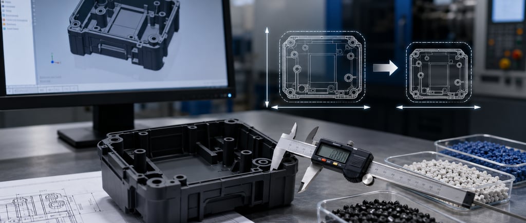
In plastic injection molding, molten plastic material is filled into the mold cavity and then solidifies as it cools. During cooling, the plastic material decreases in volume. This reduction is called shrinkage.
If this shrinkage rate is not considered during mold design, the plastic part coming out of the mold may be smaller than the targeted final dimension. Therefore, the shrinkage allowance of the material to be used must be calculated correctly during mold design.
Shrinkage allowance may vary depending on the type of plastic material, additive ratio, part wall thickness, mold temperature, injection pressure, gate location, and flow direction.
How Is Shrinkage Allowance Calculated?
The basic calculation logic is quite simple. Since the plastic part will shrink as it cools, the mold dimension is designed slightly larger than the desired final product dimension.
Basic formula:
Mold Dimension = Final Part Dimension × (1 + Shrinkage Rate / 100)
For example, if the final part dimension will be 100 mm and the shrinkage rate of the material to be used is 1%:
Mold Dimension = 100 × 1.01 = 101 mm
In this case, the mold cavity is designed at approximately 101 mm. After the part cools, it approaches the final dimension of approximately 100 mm.
However, in real production, shrinkage allowance is not only a mathematical ratio. Part geometry, wall thickness, material brand, process parameters, and flow direction must be evaluated together.
Approximate Mold Shrinkage Rates by Material
The values below are approximate reference values used in plastic injection mold design. The exact shrinkage allowance may vary depending on the material brand, additive ratio, part wall thickness, gate location, mold temperature, and process conditions.
PS / Polystyrene
Approximate shrinkage allowance: 0.30% - 0.60%
PP / Polypropylene
Approximate shrinkage allowance: 0.60% - 2.00%
PP GF30 / 30% Glass Fiber Reinforced Polypropylene
Approximate shrinkage allowance: around 0.16% in the flow direction, around 1.05% perpendicular to the flow direction
ABS
Approximate shrinkage allowance: 0.40% - 0.70%
PE / Polyethylene
Approximate shrinkage allowance: 2.00% - 3.00%
PVC / Polyvinyl Chloride
Approximate shrinkage allowance for rigid PVC: 0.50% - 0.80%
Approximate shrinkage allowance for flexible PVC: 1.00% - 5.00%
PA6 / Polyamide 6
Approximate shrinkage allowance: 0.80% - 1.40%
PA6 GF30 / 30% Glass Fiber Reinforced Polyamide 6
Approximate shrinkage allowance: 0.40% - 0.80%
PA66 / Polyamide 66
Approximate shrinkage allowance: 0.80% - 1.60%
PA66 GF30 / 30% Glass Fiber Reinforced Polyamide 66
Approximate shrinkage allowance: 0.20% - 0.40%
PC / Polycarbonate
Approximate shrinkage allowance: 0.50% - 0.70%
PC-ABS
Approximate shrinkage allowance: 0.50% - 0.70%
PMMA / Polymethyl Methacrylate
Approximate shrinkage allowance: 0.40% - 0.70%
POM / Polyoxymethylene
Approximate shrinkage allowance: 1.70% - 2.00%
PBT / Polybutylene Terephthalate
Approximate shrinkage allowance: 0.90% - 1.80%
PBT GF30 / 30% Glass Fiber Reinforced PBT
Approximate shrinkage allowance: 0.30% - 0.70% in the flow direction, 0.50% - 1.00% perpendicular to the flow direction
PPS GF40 / 40% Glass Fiber Reinforced PPS
Approximate shrinkage allowance: 0.10% - 0.30%
PPO / Polyphenylene Oxide
Approximate shrinkage allowance: 0.50% - 0.70%
PEI / Polyetherimide
Approximate shrinkage allowance: 0.50% - 0.70%
These values can be used as preliminary references for mold design. For plastic parts with tight tolerances, trial production should be carried out and necessary mold revisions should be evaluated according to measurement results.
Why Does Shrinkage Allowance Change in Glass Fiber Reinforced Materials?
The shrinkage behavior of glass fiber reinforced plastics is different from standard materials. Glass fiber reduces the shrinkage of the plastic material; however, the shrinkage rate may differ in the flow direction and perpendicular to the flow direction.
For this reason, using only a single shrinkage rate for glass fiber reinforced materials may not always provide accurate results. The flow direction of the part, gate location, and product geometry should be carefully evaluated during the design stage.
Especially in technical materials such as PA6 GF30, PA66 GF30, PBT GF30, or PPS GF40, trial production and measurement reports are highly important for dimensional stability.
Factors Affecting Shrinkage Allowance
The shrinkage rate of a plastic part does not depend only on the material type. The same material may show different shrinkage behavior under different production conditions.
The main factors affecting shrinkage allowance are:
Type of plastic material and additive ratio
Part wall thickness
Mold temperature
Injection pressure
Holding pressure and holding time
Cooling time
Gate location
Flow direction
Part geometry
Moisture content of the material
Therefore, catalog values should be taken as a starting point when calculating shrinkage allowance, and the results should be verified with real production data.
Gri Kalıp’s Approach to Shrinkage Allowance
At Gri Kalıp ve Plastik A.Ş., we evaluate shrinkage allowance in plastic injection mold design together with the product’s application, material type, part geometry, and production conditions.
Before starting mold design, the material to be used is clarified. Then, mold dimensions are determined by considering the material’s technical data, flow direction, wall thickness, and critical dimensions.
For tight-tolerance parts, we do not rely only on theoretical shrinkage values. Final dimensional accuracy is achieved through trial production, measurement reports, and necessary mold revisions.
Conclusion
Shrinkage allowance in plastic parts is one of the most critical calculations in mold design. Incorrectly calculated shrinkage allowance may cause dimensional errors, assembly problems, and mold revisions in mass production.
Each plastic material has different shrinkage behavior. PP, ABS, PC, PA, POM, PBT, and glass fiber reinforced engineering plastics all have different shrinkage rates. Therefore, material technical data, part design, and process conditions should be evaluated together for accurate results.
For a successful plastic injection mold, shrinkage allowance should not be considered only as a table value. It is an important design parameter that must be verified with engineering experience.
Frequently Asked Questions
What is shrinkage allowance in a plastic part?
Shrinkage allowance is the rate at which plastic material shrinks as it cools after being removed from the mold. In mold design, the mold cavity is prepared larger than the final product dimension by taking this rate into account.
Is shrinkage allowance the same for every plastic material?
No. Each plastic material has a different shrinkage rate. Materials such as PP, ABS, PC, PA, POM, and PBT shrink at different rates.
Does glass fiber reinforcement reduce shrinkage allowance?
Generally, yes. Glass fiber reinforcement reduces the shrinkage rate of plastic material. However, different shrinkage values may occur in the flow direction and perpendicular to the flow direction.
What happens if shrinkage allowance is calculated incorrectly?
The part may not come out at the desired dimensions. This may cause assembly incompatibility, dimensional deviation, quality problems, and the need for mold revision.
Are table values sufficient for shrinkage allowance calculation?
Table values are useful as a starting point. However, for accurate results, material technical data, part geometry, process parameters, and trial production measurements should be considered.
Site Map
Home | About Us | Capabilities | Projects | Human Resources | Contact
CONTACT
Subscribe
+90 212 485 41 41
info@grikalip.com.tr
© 2024. All rights reserved.