INFO@GRIKALIP.COM.TR - GET A QUOTE FOR YOUR PROJECTS BY CONTACTING US - INFO@GRIKALIP.COM.TR
The Most Common Mistakes in Plastic Part Design
Design mistakes made before mold manufacturing can lead to high revision costs. In this article, we explain the key principles that should be considered during the design stage.
6/29/20268 min read
The Most Common Mistakes in Plastic Part Design
Meta Title: The Most Common Mistakes in Plastic Part Design | Gri Kalıp
Meta Description: Design mistakes in plastic injection molding can lead to mold revisions, dimensional problems, and high production costs. Explore the key points to consider for proper plastic part design.
URL Slug: the-most-common-mistakes-in-plastic-part-design
Blog Card Short Description: Design mistakes made before mold manufacturing can lead to high revision costs. In this article, we examine the key principles and most common mistakes to consider in plastic injection part design.
Why Should Plastic Part Design Be Planned Correctly Before Mold Manufacturing?
In plastic injection molding, producing a successful result does not depend only on manufacturing a good mold. In order for the mold to work correctly and for the plastic part to be produced with high quality, the product design must be suitable for injection molding.
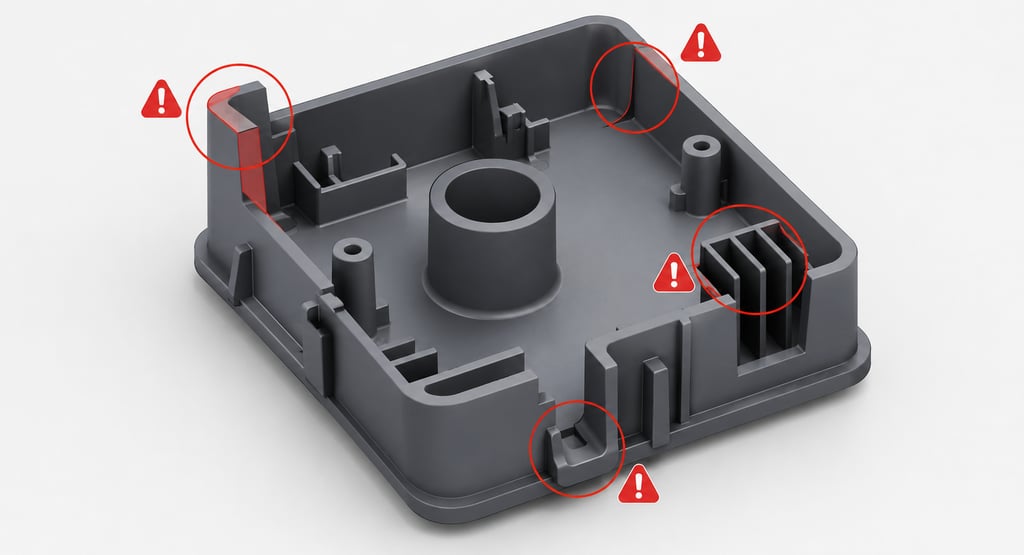
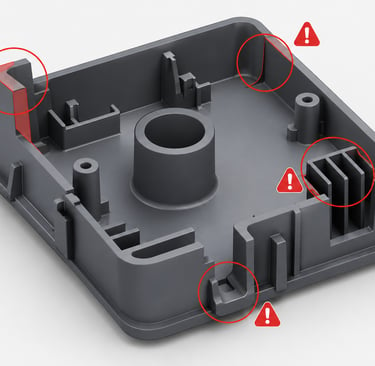
A plastic part may look simple from the outside; however, many technical details such as wall thickness, draft angles, rib structures, screw bosses, clip details, gate location, shrinkage allowance, and demolding direction must be planned correctly during the design stage.
If design mistakes are noticed after the mold has been manufactured, they can lead to serious costs. In this case, not only the product data but also the manufactured mold may need revision. This means time loss, additional labor, production delays, and customer dissatisfaction.
For this reason, plastic part design should be evaluated not only from an aesthetic or functional perspective, but also in terms of manufacturability.
1. Unbalanced Wall Thickness
One of the most common mistakes in plastic part design is unbalanced wall thickness. When some areas of the part are designed too thick and others too thin, quality problems may occur during production.
Thick sections cool more slowly and may cause sink marks, internal voids, surface waviness, or longer cycle times. Thin sections, on the other hand, make it more difficult for the plastic material to flow inside the mold and may cause short shot problems.
In a proper design, part wall thickness should be as balanced as possible. Unnecessary thick areas should be cored out, and if strength is required, ribs or support structures should be used instead of simply increasing thickness.
For example, instead of a large and thick body section, a lighter and more manufacturable part can be achieved with a thinner wall thickness and properly positioned ribs.
2. Insufficient Draft Angle
Plastic injection molded parts must have a suitable draft angle in order to be released from the mold easily. Draft angle is the slight inclination given to surfaces in the direction of demolding.
In parts with insufficient draft angle, mold release becomes difficult. This may cause surface friction marks, deformation, ejector marks, or part sticking. Draft angle becomes even more critical especially in deep-walled parts, textured surfaces, or parts with high surface quality expectations.
Parts designed without sufficient draft angle may require additional moving mechanisms during mold manufacturing. This increases mold cost.
Therefore, the demolding direction should be determined from the beginning of the plastic part design process, and all surfaces should be evaluated according to this direction.
3. Incorrect Rib Design
Ribs are support elements used to increase strength and reinforce the structure of plastic parts. However, if ribs are designed incorrectly, they may cause quality problems.
Ribs that are too thick may create sink marks on the outer surface of the part. Ribs that are too thin may not provide sufficient strength or may create filling problems. In addition, if rib corner transitions are sharp, stress concentration may occur and the part may become more prone to breaking.
In general, rib thickness should be designed in balance with the main wall thickness. Suitable radii should be used at rib base transitions, and rib placement should be planned according to the function of the part.
Correct rib design provides strength without increasing part weight. Incorrect rib design may cause problems both during production and during use.
4. Incorrect Screw Boss Design
Screw bosses are one of the most commonly used connection details in plastic parts. However, incorrect screw boss design may cause cracking, sink marks, breakage, or assembly problems.
If the screw boss is designed too thick, sink marks may appear on the outer surface. If it is designed too thin, cracking or breakage may occur during screw assembly. If there is not enough support around the screw boss, the part may deform during assembly.
Correct wall thickness, suitable rib support, proper hole diameter, and appropriate corner radii should be used in screw boss design. In addition, the screw type and assembly force should be known during the design stage.
In design, it is not enough to simply place the screw hole. The manufacturability and long-term durability of the screw boss must also be considered.
5. Sharp Corners and Lack of Radii
Sharp corners are an important source of problems in plastic part design. Sharp corners may make plastic flow more difficult, create stress concentration inside the mold, and increase the risk of part breakage.
Sharp internal corners also make the mold machining process more difficult. More precise machining may be required in CNC or EDM operations. This can increase mold cost.
Suitable radii should be used wherever possible. Radii improve plastic flow and increase the mechanical strength of the part. Corner transitions should be designed carefully, especially in load-bearing, clipped, or impact-resistant plastic parts.
6. Incorrect Clip and Snap-Fit Design
Clips, tabs, and snap-fit details are frequently used in plastic parts. However, if these details are designed without considering material flexibility, wall thickness, working direction, and assembly force, breakage or assembly problems may occur.
If clips are designed too rigid, they may break during assembly. If they are designed too flexible, they may not provide sufficient holding force. The plastic material to be used is also very important at this point. For example, the clip behavior of a more flexible material such as PP is not the same as that of more rigid materials such as ABS or PC.
In clip design, material selection, deflection distance, corner radii, and assembly direction should be evaluated together. The demolding direction should also not be forgotten. Clip details that create undercuts may require sliders, moving cores, or additional mechanisms in the mold.
7. Not Considering the Demolding Direction
One of the most critical subjects in plastic part design is the demolding direction. If this issue is not considered while designing the product, undercuts may occur on the part. Undercuts prevent the part from being removed from a simple two-plate mold.
In this case, sliders, moving cores, or moving mechanisms must be added to the mold. This increases mold cost, extends production time, and raises maintenance requirements.
Some undercuts may be necessary for the function of the product. However, unnecessary undercuts should be avoided. During the design stage, the mold opening direction should be determined and the part should be optimized according to this logic.
A manufacturability analysis before mold manufacturing helps detect such problems early.
8. Ignoring Shrinkage Allowance
Every plastic material shrinks to a certain extent during cooling. Therefore, shrinkage allowance must be considered in mold design. If mold manufacturing starts before the material is finalized during the design stage, dimensional problems may occur.
PP, ABS, PC, PA, POM, and glass fiber reinforced materials all have different shrinkage rates. Even within the same material group, shrinkage behavior may change depending on additive ratio, brand, and process conditions.
If shrinkage allowance is not calculated correctly, part dimensions may fall outside the targeted tolerances. This can cause serious problems, especially in assembled products.
For this reason, the material to be used in plastic part design should be determined as early as possible, and mold dimensions should be planned accordingly.
9. Designing Without Considering the Material
One of the major mistakes in plastic part design is assuming that all materials will behave in the same way. However, every plastic material has different mechanical strength, flexibility, temperature resistance, shrinkage rate, and flow behavior.
For example, if the wrong material is selected for a clip that needs to flex, the part may break. If a material with low temperature resistance is selected for a product that will be used at high temperatures, the product may deform. In transparent parts, surface quality and internal stress become more critical.
Proper design should be made according to the technical properties of the material to be used. Material and design are not independent decisions.
10. Ignoring Assembly and Usage Conditions
A plastic part should be evaluated not only during production but also during use. If the part will be assembled with another product, assembly tolerances, screw connections, clip forces, and working environment should be considered during the design stage.
Some parts may be exposed to temperature changes, impact, chemicals, UV light, or continuous mechanical load. Designs made without considering these conditions may create problems in the field.
During the design stage, the following questions should be asked:
Where will the part be used?
In which temperature range will it operate?
Will it be assembled with other parts?
Will it carry impact or load?
Will there be chemical contact?
Will it be exposed to sunlight outdoors?
The answers to these questions directly affect both material selection and part design.
What Should Be the Correct Approach in Plastic Part Design?
Successful plastic part design requires the product to be both functional and manufacturable. Design should not be evaluated only as a model that looks good on a computer screen. The moldability, cooling behavior, demolding, dimensional stability, and mass production performance of the part should be considered together.
In a correct design approach:
Wall thickness should be balanced.
Draft angles should be sufficient.
Sharp corners should be avoided.
Ribs should be designed with proper proportions.
Screw bosses should be supported.
Clip details should be suitable for the selected material.
Undercuts should be minimized.
Shrinkage allowance should be taken into account.
Material selection should be evaluated together with the design.
Assembly and usage conditions should be considered.
If these principles are applied correctly before mold manufacturing begins, the need for revision decreases and production becomes more efficient.
Gri Kalıp’s Approach to Plastic Part Design
At Gri Kalıp ve Plastik A.Ş., we consider part design one of the most critical stages of plastic injection molding projects. Before moving into mold manufacturing, product data is reviewed in terms of manufacturability.
Wall thickness, draft angles, undercuts, rib structures, screw bosses, gate location, shrinkage allowance, and material suitability are technically evaluated. When necessary, we provide design improvement recommendations to our customers in order to achieve more efficient, higher-quality, and longer-lasting production.
Correct plastic part design keeps mold cost under control, reduces production scrap, and ensures quality continuity in mass production.
Conclusion
Design mistakes in plastic part design can lead to serious revision costs when they are noticed after mold manufacturing is completed. Unbalanced wall thickness, insufficient draft angle, incorrect rib design, faulty screw bosses, sharp corners, undercuts, and ignoring shrinkage allowance are among the most common design problems.
For a successful plastic injection molding project, product design should be analyzed in detail before mold manufacturing begins. Correct design means higher-quality parts, lower costs, shorter production times, and more reliable mass production.
Correct engineering work carried out at an early stage in plastic part design prevents major costs that may occur later.
Frequently Asked Questions
What is the most common mistake in plastic part design?
One of the most common mistakes is unbalanced wall thickness. Very thick areas may cause sink marks, while very thin areas may lead to short shots and weak strength.
Why is draft angle important in plastic parts?
Draft angle allows the part to be removed from the mold easily. Insufficient draft angle may cause surface friction, deformation, ejector marks, and demolding problems.
How should rib design be done?
Ribs should be designed in balance with the main wall thickness. Ribs that are too thick may create sink marks, while ribs that are too thin may not provide sufficient support.
Why are sharp corners risky in plastic parts?
Sharp corners may cause stress concentration, increased breakage risk, and plastic flow problems. Using suitable radii improves both strength and manufacturability.
Why should shrinkage allowance be considered in design?
Plastic materials shrink as they cool. If shrinkage allowance is not calculated correctly, the part may not come out at the desired dimensions and assembly problems may occur.
Why is material selection important during the design stage?
Each plastic material has different flexibility, strength, shrinkage rate, and temperature behavior. Therefore, product design should be made according to the selected material.
Site Map
Home | About Us | Capabilities | Projects | Human Resources | Contact
CONTACT
Subscribe
+90 212 485 41 41
info@grikalip.com.tr
© 2024. All rights reserved.